Anterior segment (AS) optical coherence tomography (OCT) is the non-invasive technique used to analyse detailed cross-sectional images of the anterior structures of the eye. Swept source (SS) OCT at 1310nm can penetrate deeply into the eye with low levels of scatter and presents an image extending to 14.5mm into the anterior eye.
This has provided greater utilisation of OCT technology in multiple subspecialty clinics, including cataract, glaucoma and cornea [1]. Where once, OCT was primarily used for medical retina and vitreoretinal services, we are seeing a significant increase in demand for OCT in the AS specialties to aid in the diagnosis and monitoring of a wide variety of anterior diseases and pathology.
In this article, I will discuss the influence of refraction correction in SS AS-OCT measurement parameters, including how this can change the interpretation of the OCT image. We did this by comparing several AS images of the same patient captured on Heidelberg Engineering’s ANTERION, on two different modules within the device: IMAGING App and METRICS App, to determine the potential source of errors in visual analysis of patients within multiple subspecialty clinics.
Imaging app
The imaging app is the foundational component of the ANTERION. High-resolution SS OCT imaging visualises the entire AS.
METRICS app
Utilising the same high-resolution SS OCT, but with refraction correction implemented, providing a highly accurate, repeatable, radial view of the anterior chamber. This enables a comprehensive assessment of the central corneal thickness (CCT), white-to-white (WTW) distance, angle metrics including anterior chamber angle (ACA), angle opening distance (AOD) and trabecular iris space area (TISA), through to the lens thickness and vault [3].
What is refraction correction OCT?
Standard SS OCT (IMAGING App) processes the anatomical structures in such a way that it assumes the light has journeyed in a direct straight path. What really occurs is the light has passed through the semi-transparent curved medial structures of the AS, such as the cornea and lens [4]. Without considering the refractive effect of the cornea, this media causes distortion to the ‘raw’ image, and in so doing it makes the structural presentation false, and therefore any measurement parameters will inherently be inaccurate. Therefore, these parameters cannot be truly defined. Using OCT alone without refraction correction could potentially influence how we interpret the image and the initial impression it gives to the clinician on structural changes to the patient’s eye. The question is, could this alter how the patient is managed?
The most striking difference in how the OCT appears differently between refraction corrected and non-correct OCTs, and perhaps the first way to best illustrate this, is with a pseudophakic patient. This is because the distortion created in non-corrected scans gives the impression of an abnormal bowed back iris, and this feature is evident on most, if not all pseudophakic patients, and the question ‘why does the iris look like that?’ was a question posed to me by multiple clinicians when our department first started using spectral domain AS-OCT.
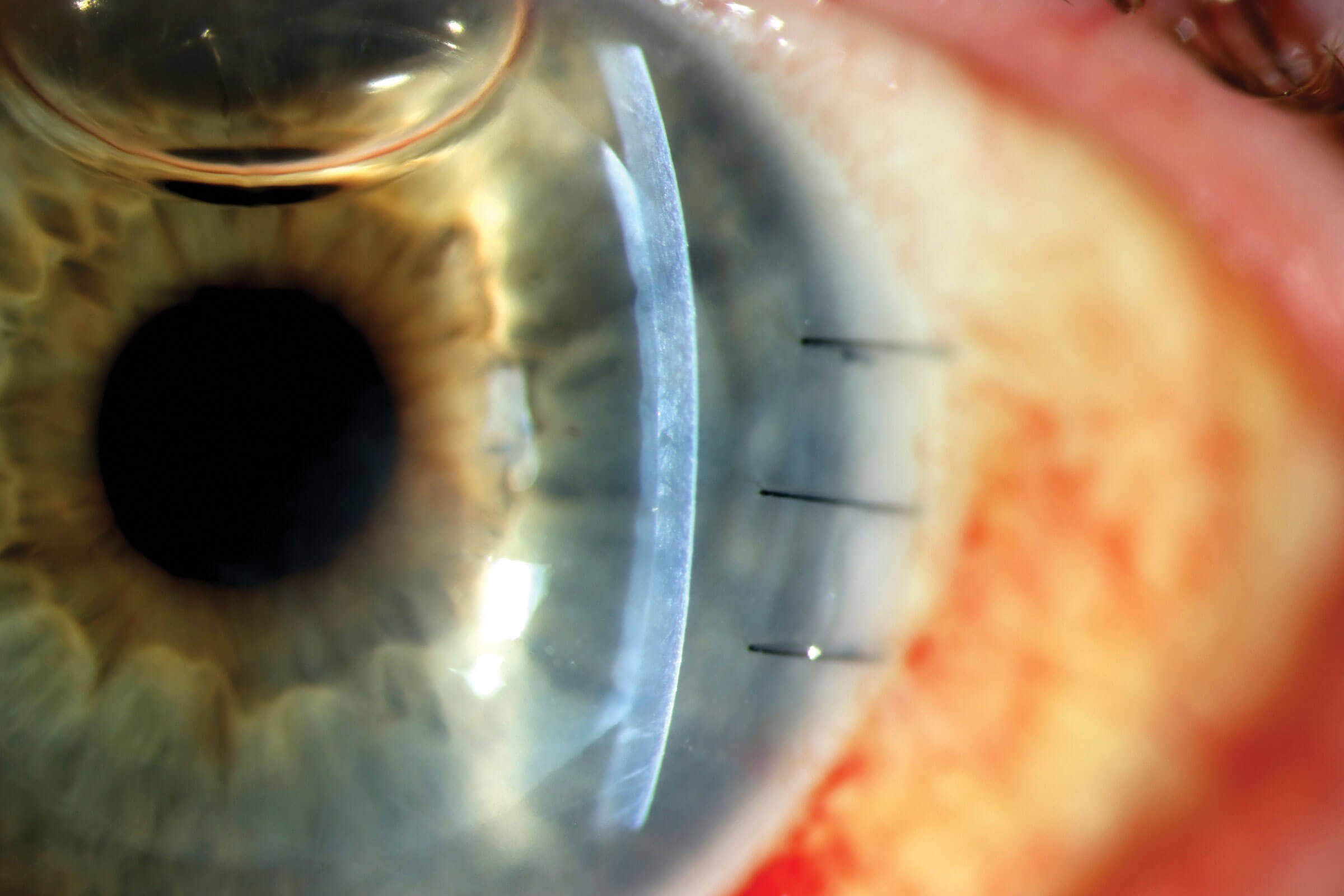
Figure 1a.
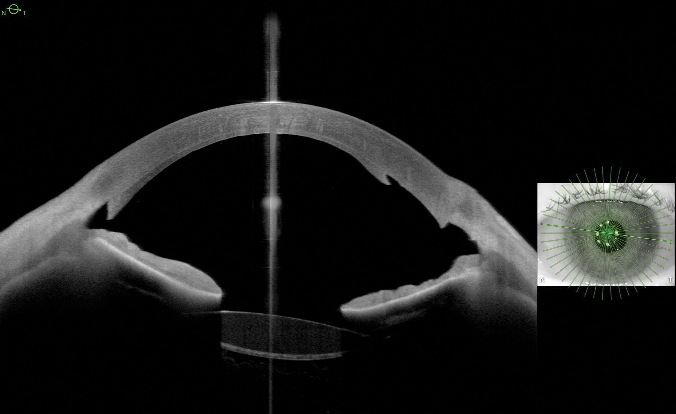
Figure 1b.
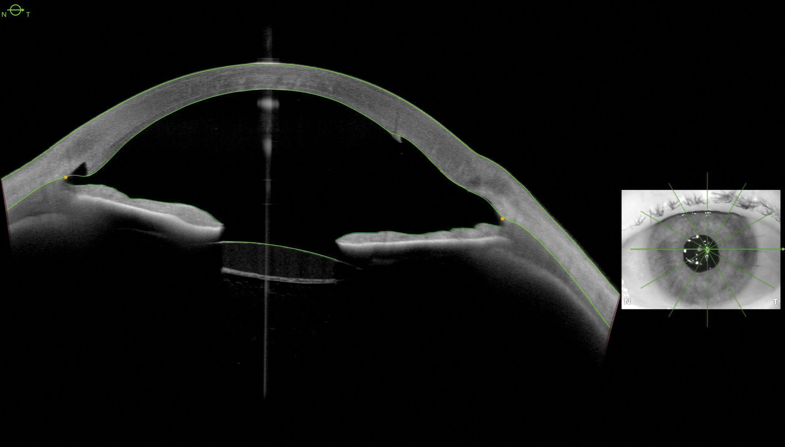
Figure 1c.
Pseudophakic patient with cornea surgery
Figure 1a (slit lamp image with fine slit illumination) is of a patient that has undergone Descemet stripping automated endothelial keratoplasty (DSAEK). Note there is still a gas bubble in the anterior chamber. Figure 1b (IMAGING app, horizontal OCT) nicely shows the graft attachment and a stable IOL. Figure 1c (METRICS app, horizontal OCT) is of the same patient taken moments later – note the typical bowing back appearance of the iris, due to the influence of the corneal refraction, has now been corrected.
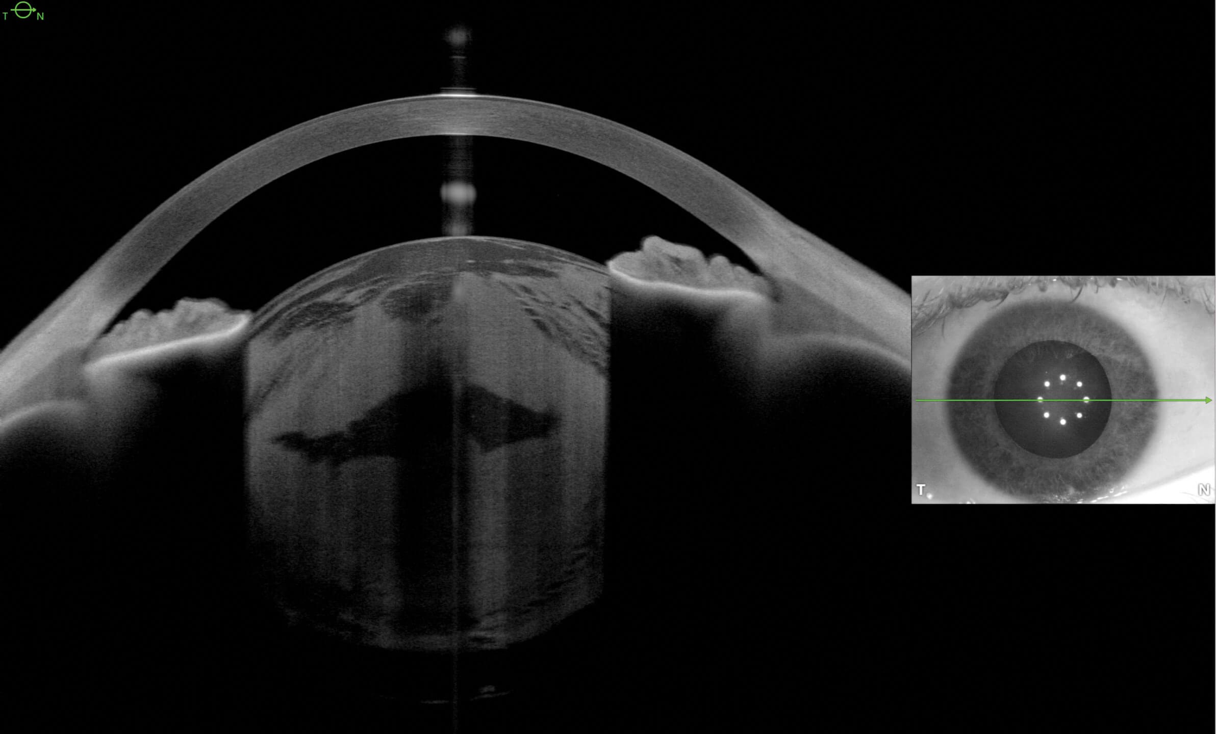
Figure 2a.
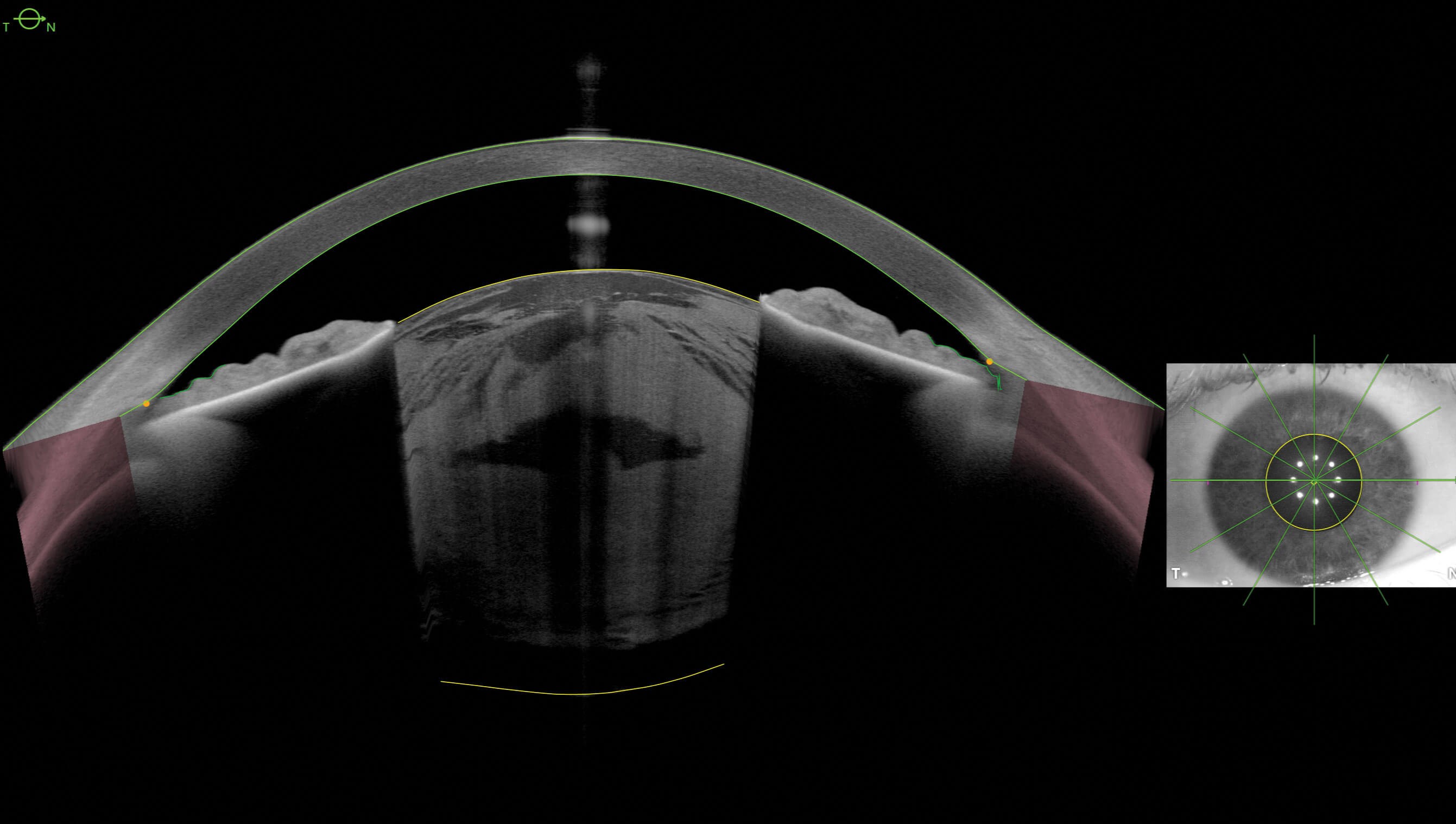
Figure 2b.
Phakic patients with cataracts
Let’s now compare Figures 1a and 1b to phakic patients with two different types of cataracts. Figure 2a (IMAGING OCT) is of a patient with a dense white cataract. Figure 2b (METRICS OCT) was taken moments later. Note how the non-refraction corrected distortion influences the appearance of the pupil size, corneal thickness, iris thickness, lens thickness and anterior chamber depth.
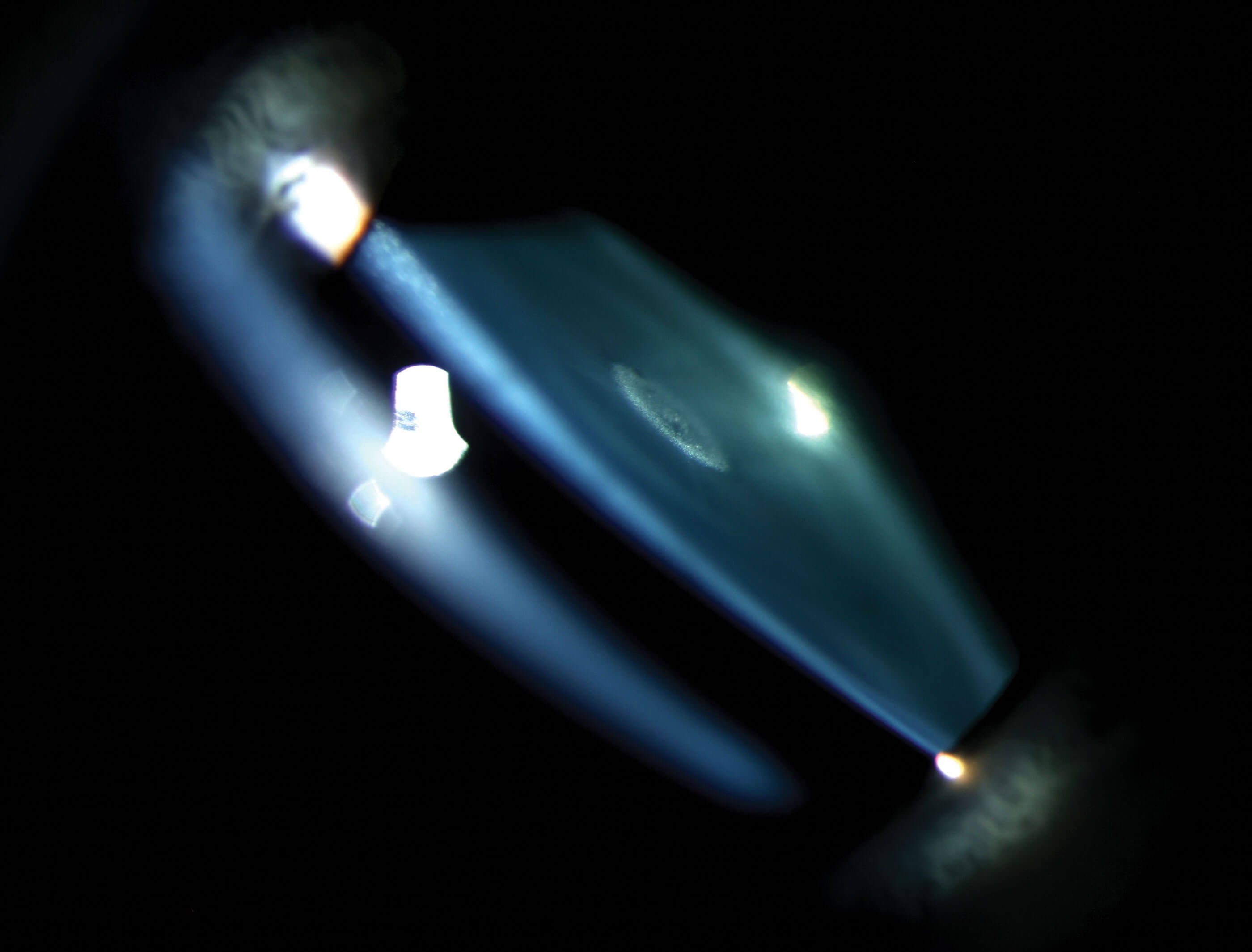
Figure 2c.
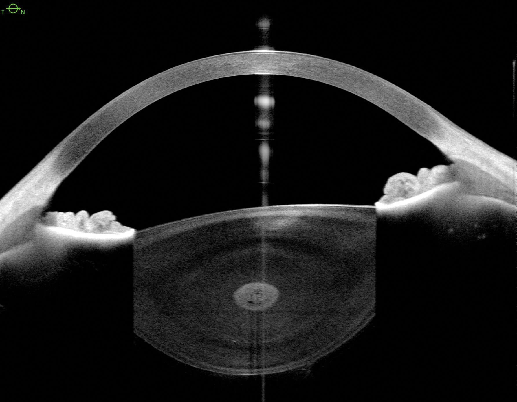
Figure 2d.
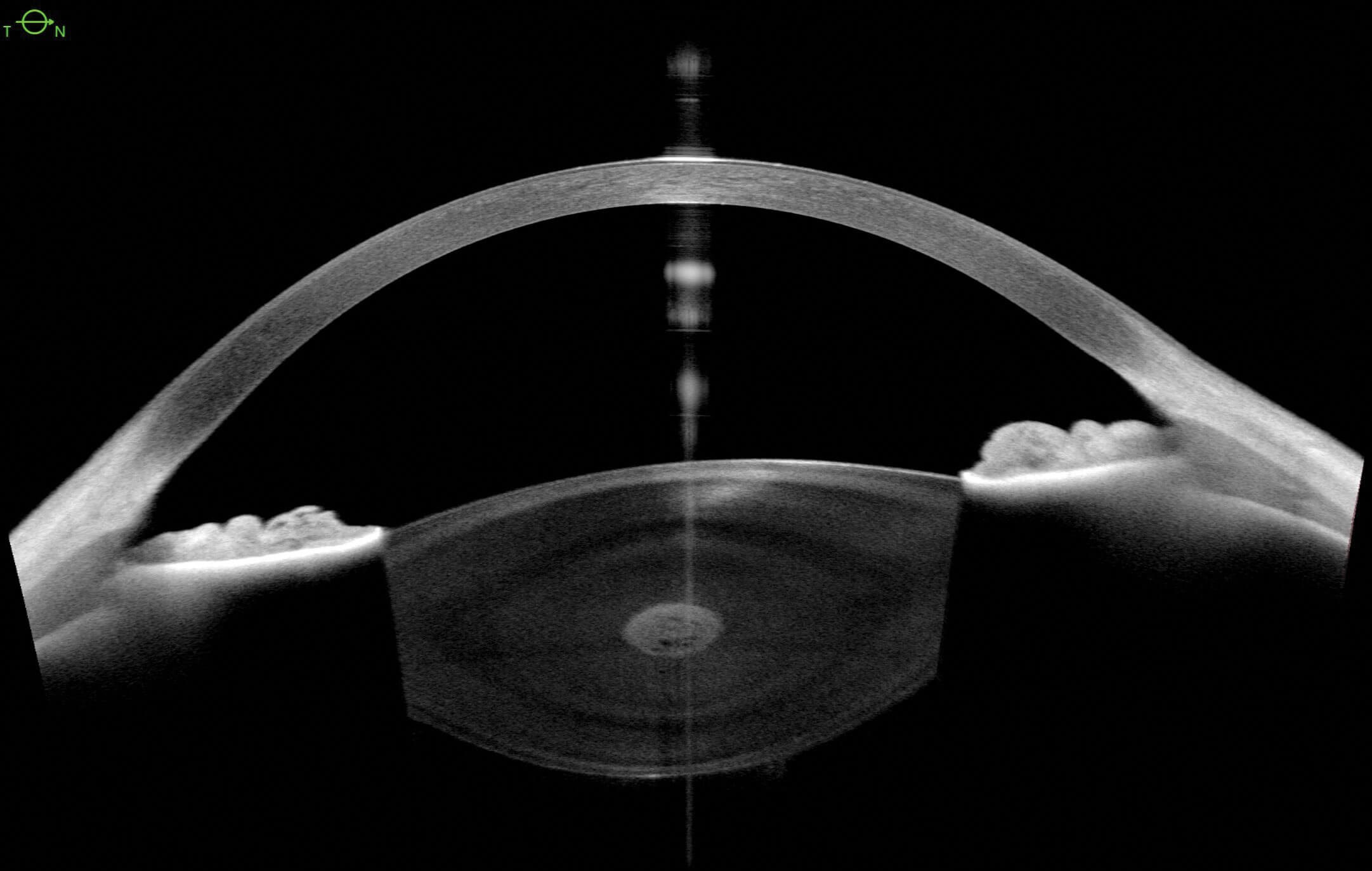
Figure 2e.
Figure 2c (slit lamp image with an optical section through a lens) highlights the location of a congenital cataract in a paediatric patient. Note the slit beam has been tilted to avoid eyelid artefact in the image as the patient struggled to keep eye open. Figure 2d (IMAGING OCT) is of the same patient. In Figure 2e (METRICS OCT) note the difference in the size of the lens – the cornea appears thicker, and the iris configuration is unusual.
These cases highlight the difference and risk of evaluation of images that are not anatomically correct. While the IMAGING does provide an excellent quality of detail, especially in the congenital cataract case, where slit lamp examination can be challenging in paediatric patients, the effect of the cornea, however, is not considered. As a result, the cornea and lens look thicker and, in the angle, especially in Figure 2b, we see that although narrow, it is open in METRICS, but appears to have some iridocorneal touch in IMAGING (Figure 2a).
Practical use in corneal services
The surgical cornea team have found this particularly useful for monitoring and aiding in the assessment of postoperative Descemet membrane endothelial keratoplasty (DMEK) surgery patients.
Post-surgery, patients come from a ward setting, on their beds in a horizontal postured position. This occurs as standard on Day 0, 1 and 3 post surgery. The patient, all being well with their graft, is further followed up on day 7, 14, 21 and 28 within the first month of surgery. At each visit, we perform SS AS-OCT on both IMAGING and METRICS.
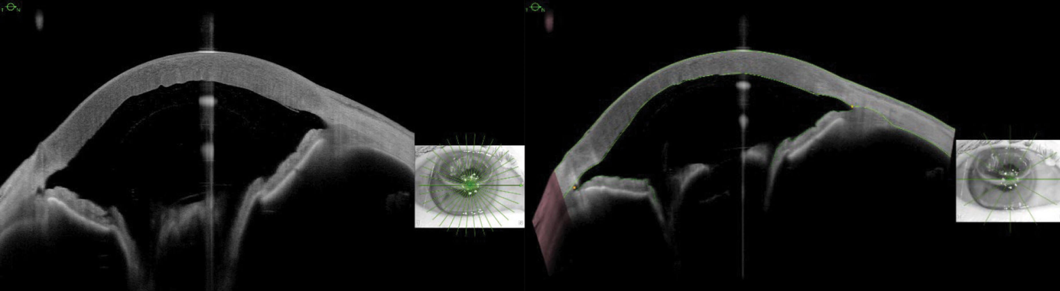
Figure 3a: Horizontal scan from radial scan pattern on IMAGING. Figure 3b: Horizontal scan from radial scan pattern on METRICS.
Figures 3a and 3b, taken simultaneously, effectively show how the refraction correction influences the thickness of the cornea on the scan. There is also significant and additional distortion caused by the SF6 gas in the anterior chamber in Figure 3a, giving the impression of a much deeper anterior chamber depth and wider iridocorneal angle, compared with Figure 3b.
Postoperative DMEK patients require strict, face-up posturing within the first week to ensure a better graft outcome. Any imaging taken at these postoperative visits must be non-invasive and swift. Utilising the IMAGING App allows for radial scan with 20+ lines. This provides excellent 360-degree visualisation of the graft attachment to look for any areas of graft detachment. Adding the METRICS App scan allows us to capture the central corneal thickness, with just a few extra seconds for the patient on the chin rest. With eye tracking enabled on METRICS, this is particularly helpful in accurately monitoring postoperative corneal thickness, especially with any associated oedema progression/regression.
Postoperative oedema in a DMEK patient
A 78-year-old female underwent a combined second eye procedure of phaco + IOL, DMEK, for her Fuch’s endothelial dystrophy, following successful right eye keratoplasty. Visual acuity in the left eye pre-surgery was 6/24 with pinhole, with a CCT of 629µm.
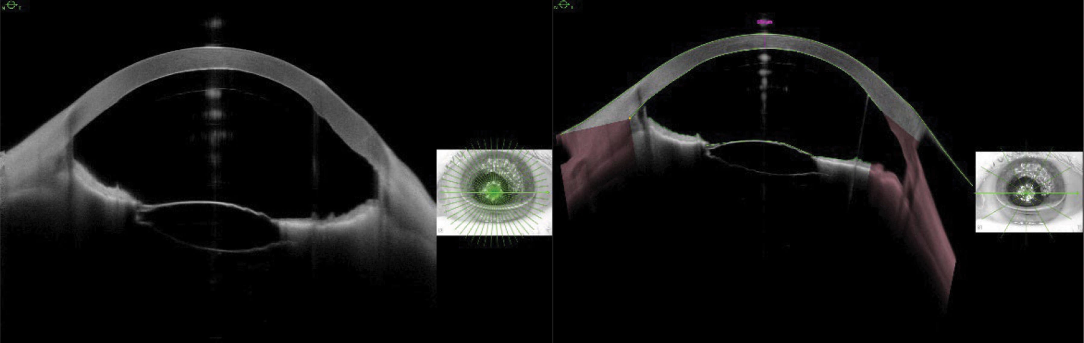
Figure 4a: IMAGING and Figure 4b: METRICS SS-OCT taken on day 0, a few hours after DMEK surgery. Central corneal thickness measurement on METRICS scan shows a measurement of 574µm. Only relative measurements are possible in IMAGING.
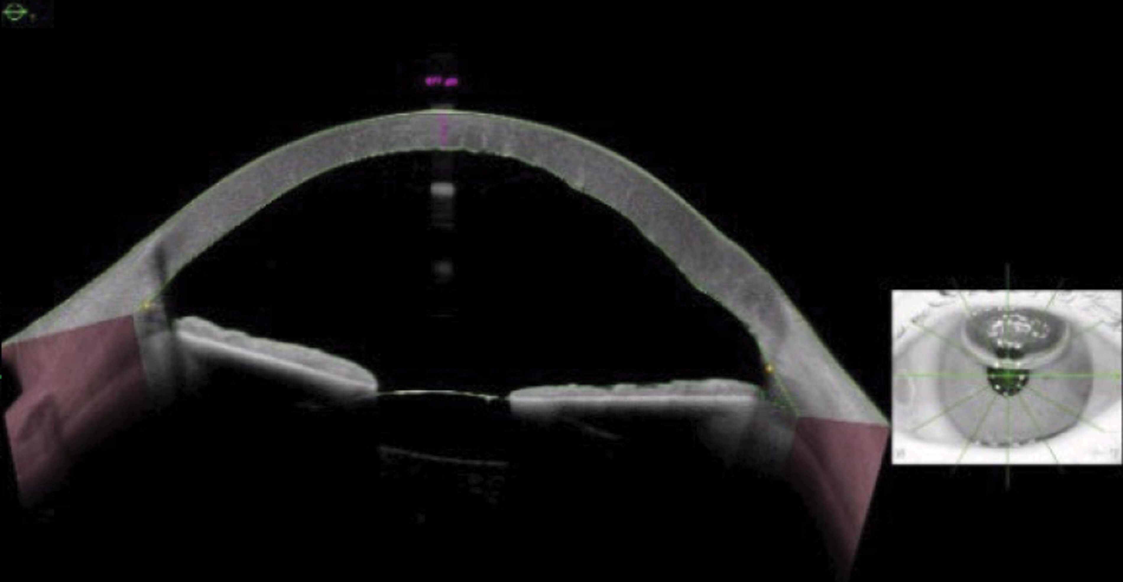
Figure 4c: Day 10, post-op, METRICS OCT with a CCT measurement of 677µm, showing improvement in the oedema, following drops regime and strict posturing compliance.
Patient’s visual acuity improved to 6/9 prior to an up-to-date refraction. Using combined IMAGING and METRICS OCT modalities enabled the clinician not only to be able to track and monitor the graft’s attachment, but also the epithelial thickness, complementing the clinical examination. It would not have been possible to measure CCT on IMAGING OCT alone. METRICS CCT parameters allowed for documentation of subtle changes in corneal thickness between postoperative visits.
Contact lens fitting in patients with keratoconus
As well as the surgical cornea clinics, AS-OCT has been adopted in optometry contact lens fitting clinics when analysing a fit of XL scleral contact lenses. The minimum central clearance varies between lenses, and without the OCT it can be much more difficult to assess the clearance precisely especially for lenses requiring minimal clearance like the XL lenses.
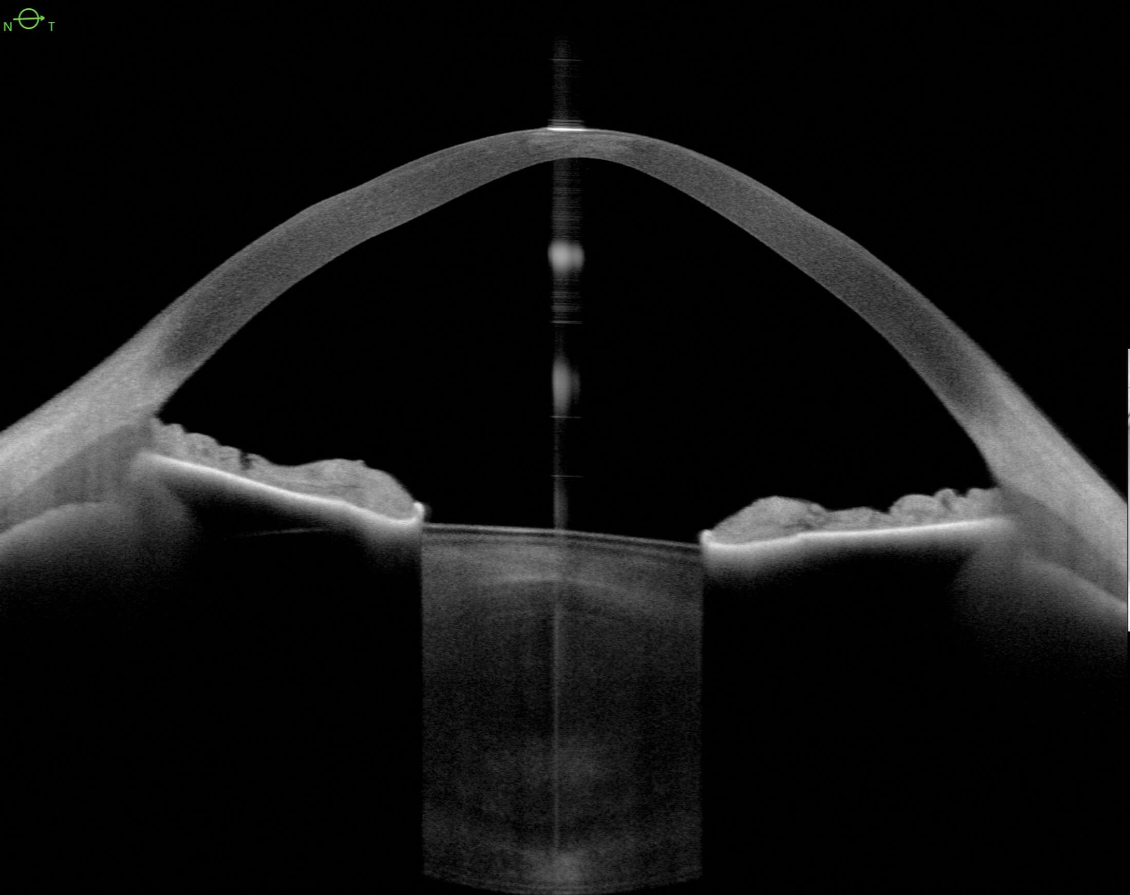
Figure 5a: IMAGING OCT of a patient with keratoconus.
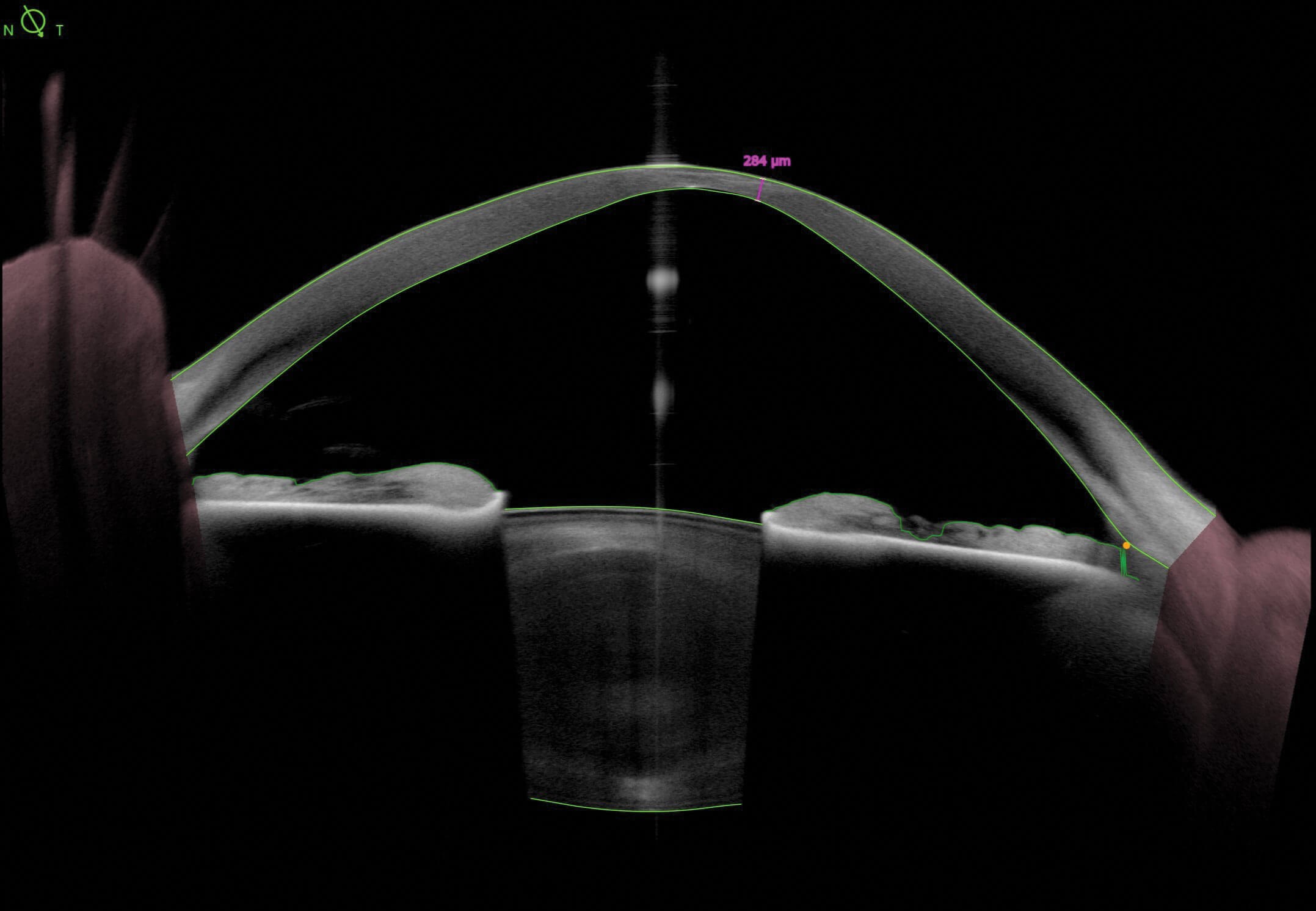
Figure 5b: METRICS OCT of the same patient.
We were able to measure the thinnest point of the cornea. See Figures 5a and 5b and note how the distortion on the IMAGING gives the impression of a thicker cornea and wider iridocorneal angle. The cone itself also appears steeper in Figure 5a.
The optometrist would first assess by instilling fluorescein when the patient inserts the lens and judging the fluorescein pattern, usually with a corneal section and comparing this to the width of the contact lens to get an estimate of clearance. When assessing on the slit lamp, lenses can be mistakenly fitted too steep, as it can often appear to be touching the cornea at the highest point (minimal discernible NAFL present) meaning you would opt for the steeper lens to avoid central touch. Being able to measure this point accurately on METRICS allows for reassurance that there is in fact clearance. Using OCT without refraction correction would not be able to measure distances in microns.
Advanced keratoconic patients also may have excessive pooling around the cone, masking an exceedingly small area of touch at the highest point. So, in this instance, the lens may be fitted too flat.
Some patients that are longstanding wearers attend and we are unable to flush enough fluorescein under the lens to assess it properly, therefore, to be able to use OCT METRICS allows us to assess the central fit without requesting that the patient removes and inserts again with fluorescein.
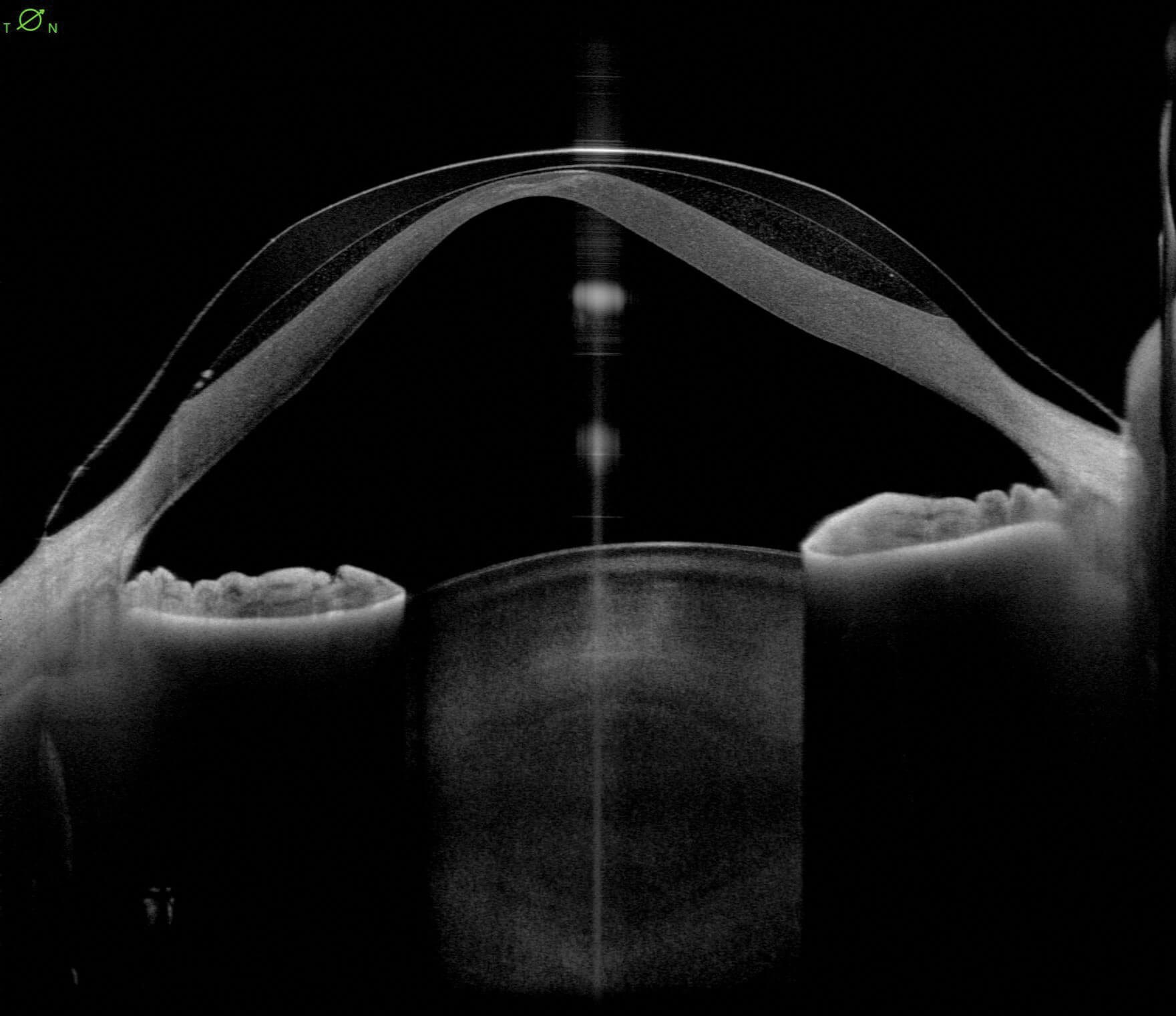
Figure 6a: IMAGING OCT inferior temporal to superior nasal scan showing an XL lens on a keratoconic right eye.
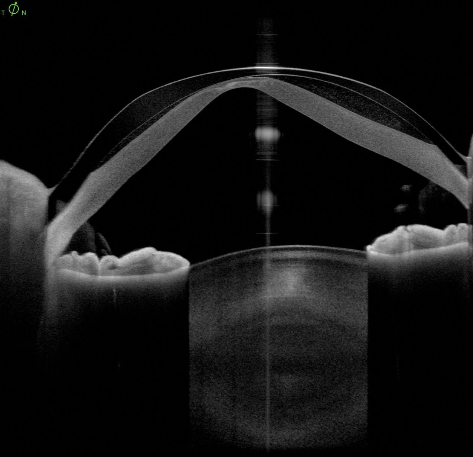
Figure 6b: IMAGING OCT slightly more vertical scan from the same radial scan patter showing lens touch.
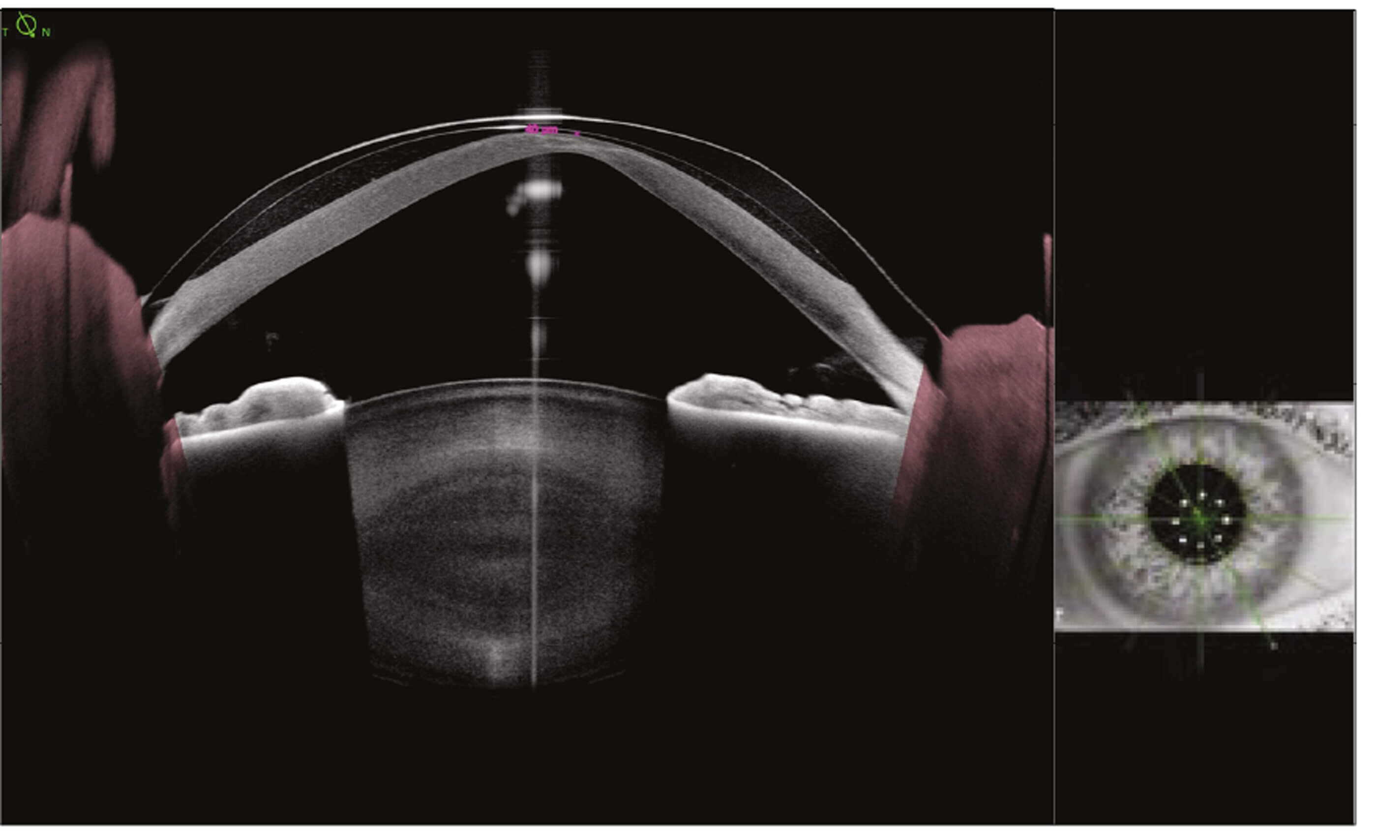
Figure 6c.
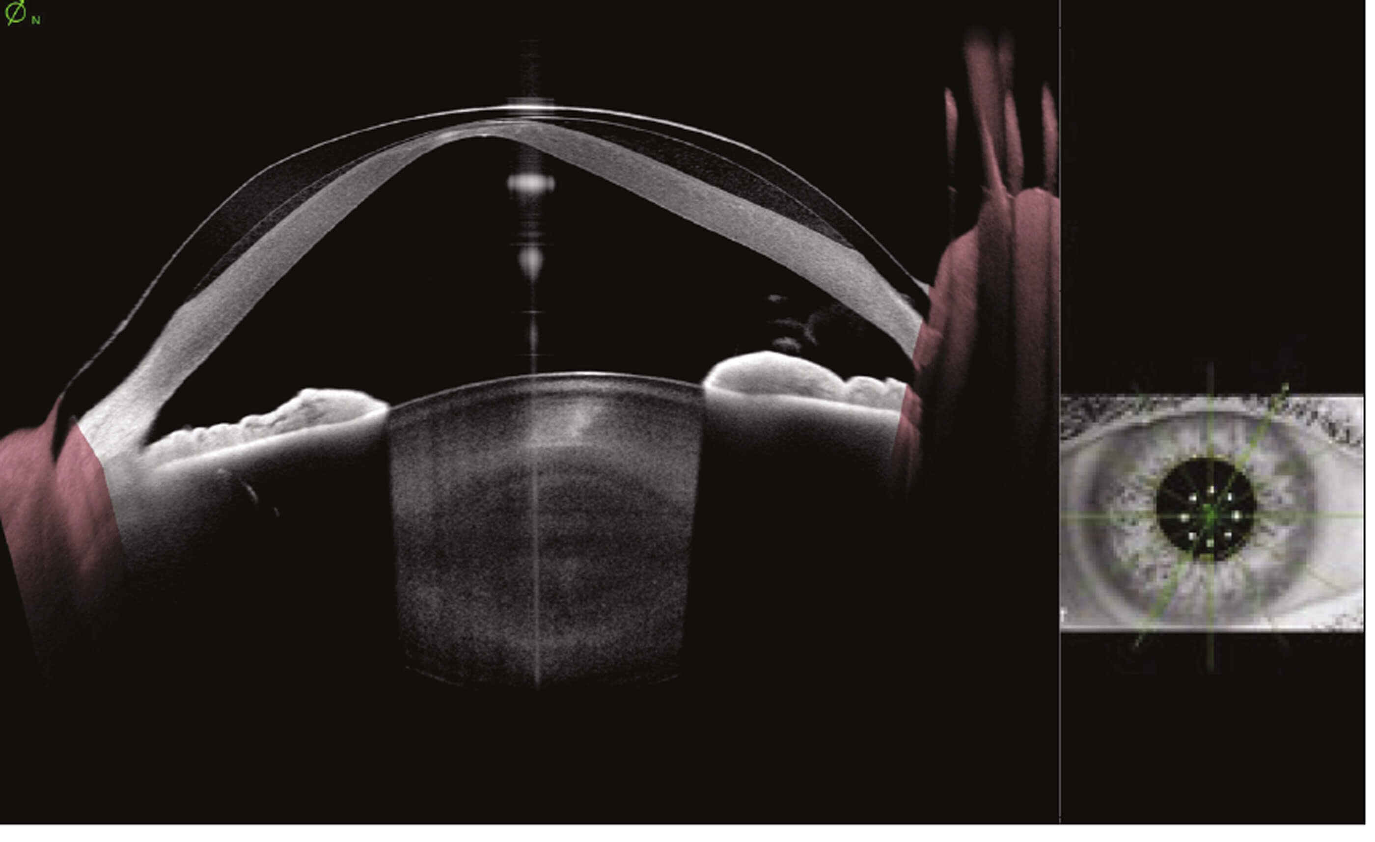
Figure 6d.
In Figures 6a and 6b, note there are no calliper options in microns available to measure the lens clearance. Figure 6c shows cross sectional from superior temporal to inferior nasal of the same patient, with a clearing of 40µm measured at the steepest point of the cornea. Figure 6d shows the cross section from inferior temporal to superior nasal showing evidence of touch between the lens and the steepest point of the cornea. This demonstrates why it is important to capture radial scan patterns.
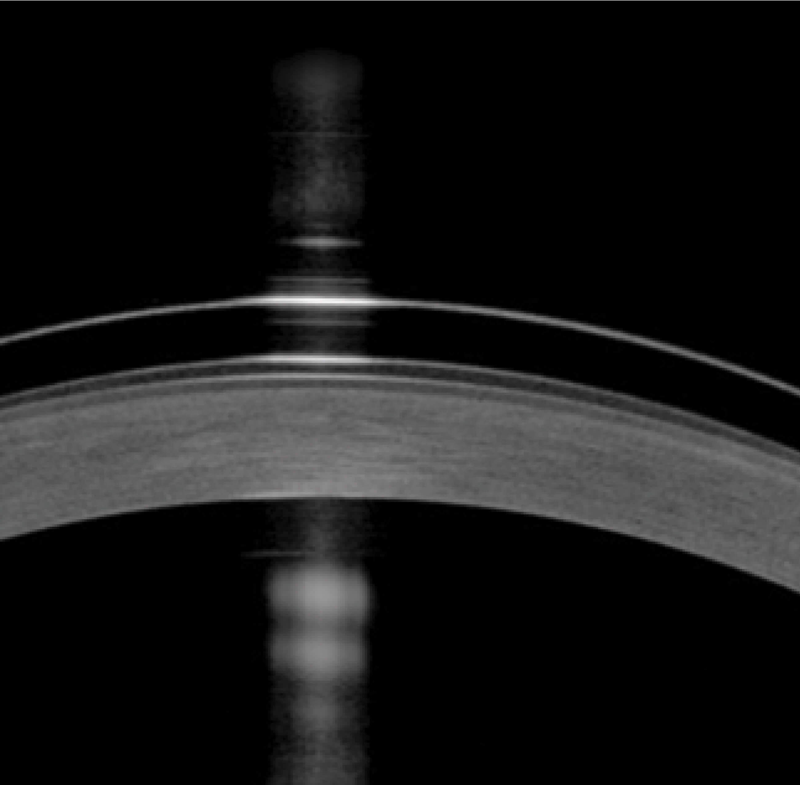
Figure 7a: IMAGING OCT showing a very close clearance of the lens to the cornea.
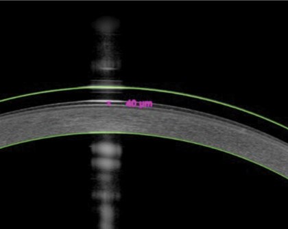
Figure 7b: METRICS OCT of the same patient with a measurement calliper showing that the clearance is at optimum level at the steepest point of the cornea between 30–50um.
Refraction correct OCT in METRICS has become an essential tool we use during fitting. It allows us to ensure we are accurately measuring the central fitting of corneal scleral and semi-scleral designs and therefore avoiding complications such as corneal erosion or hypoxia.
Practical use in the glaucoma service
Even before the days of our department having access to SS OCT, we were regularly using AS OCT with spectral domain. A baseline scan of the anterior chamber angle using the AS module on the Heidelberg Engineering SPECTRALIS platform became customary practice for scanning new patient glaucoma referrals.
Patients referred for suspected narrow angle glaucoma
Example 1
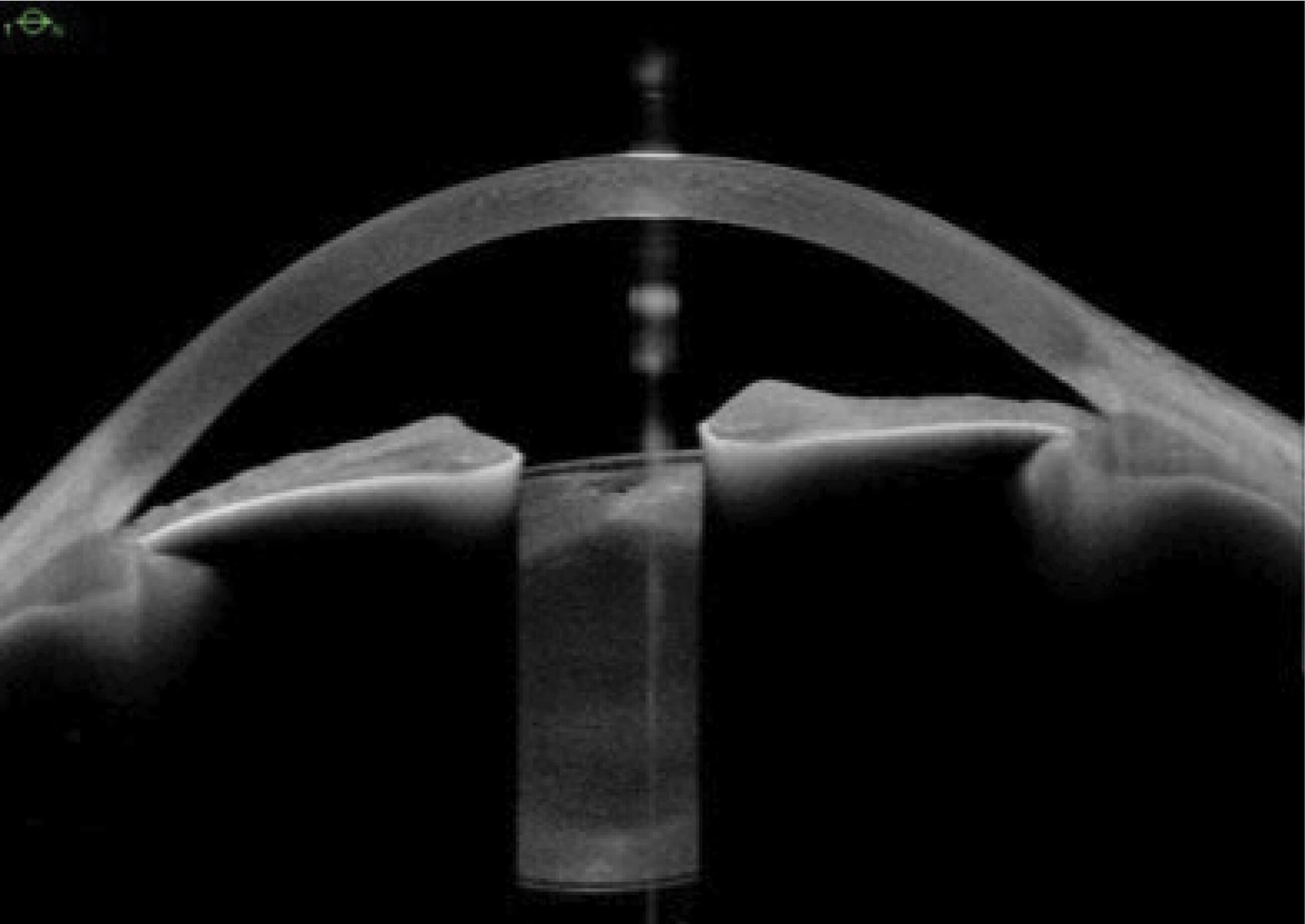
Figure 8a: Horizontal IMAGING OCT. Note the flat appearance of the iris.
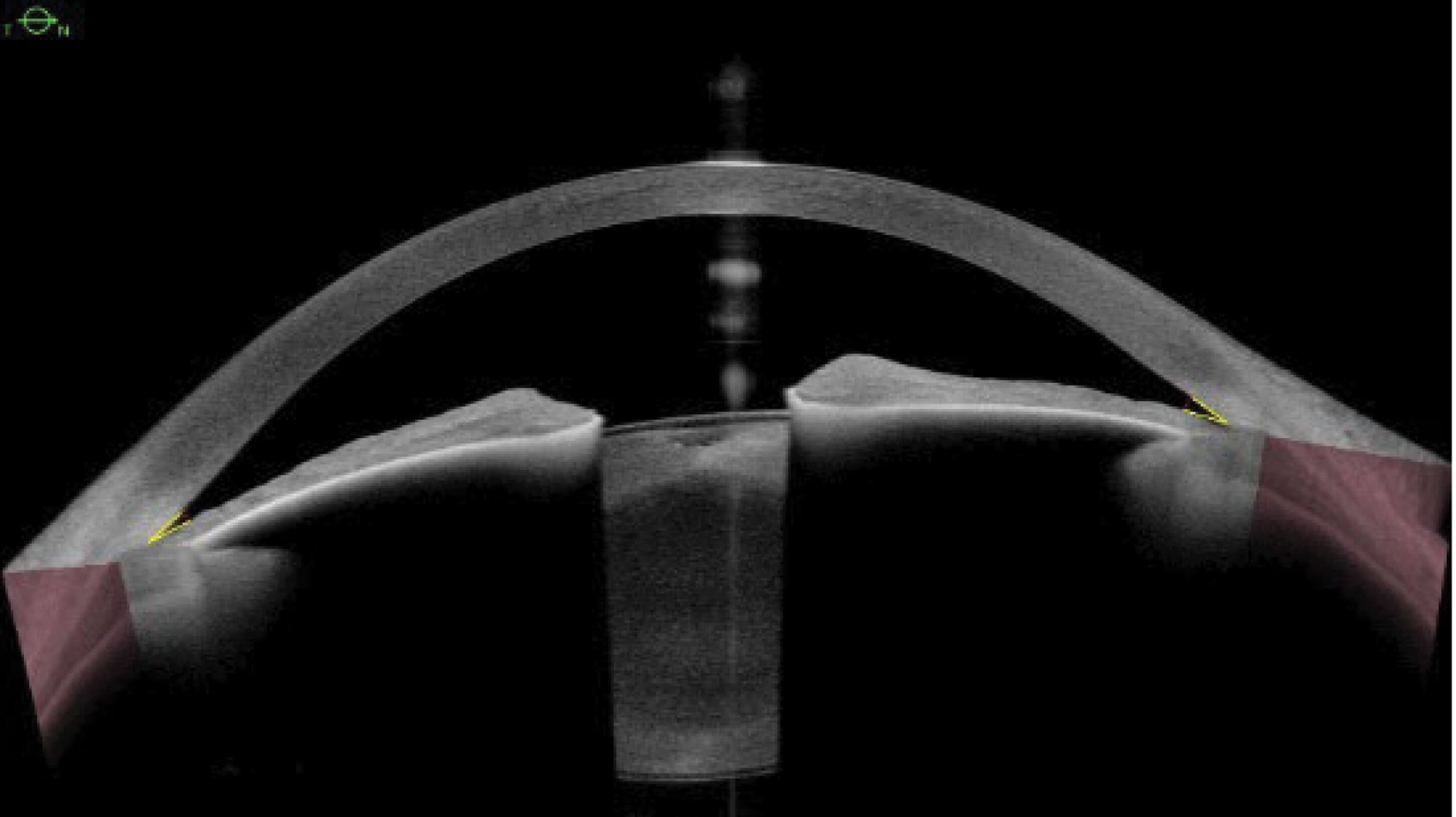
Figure 8b: METRICS OCT of the same patient (8a). Note the subtle changes of the angle, giving an accurate presentation of the structure and clinical picture of the patient.
Automatic scleral detection is used to place scleral spur angle parameters at 500µm (yellow lines) and the anterior chamber opening depth at 500µm (red dotted lines). The temporal angle is calculated at 16 degrees with an opening of 0.14mm, and the nasal angle is calculated at 20 degrees with an opening of 0.18mm.
Example 2
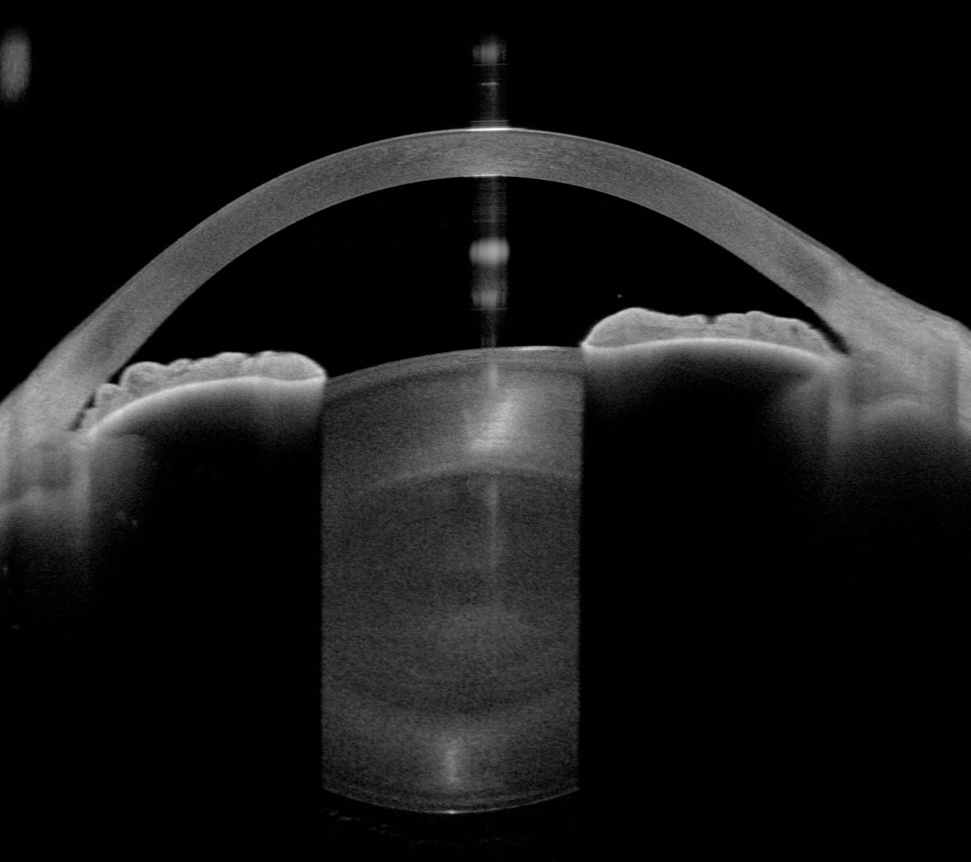
Figure 9a: Horizontal IMAGING OCT.
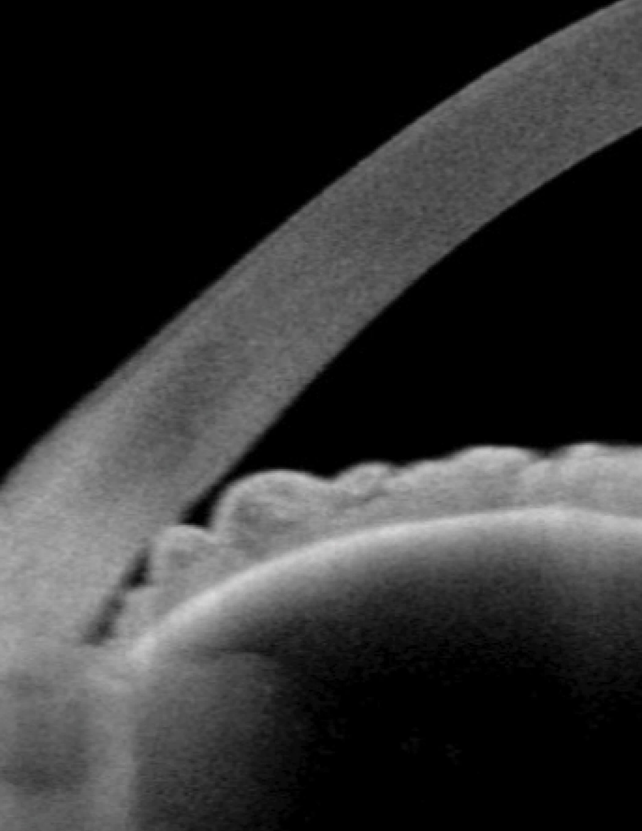
Figure 9b: Magnified view of the temporal IMAGING OCT angle revealing possible iridocorneal touch.
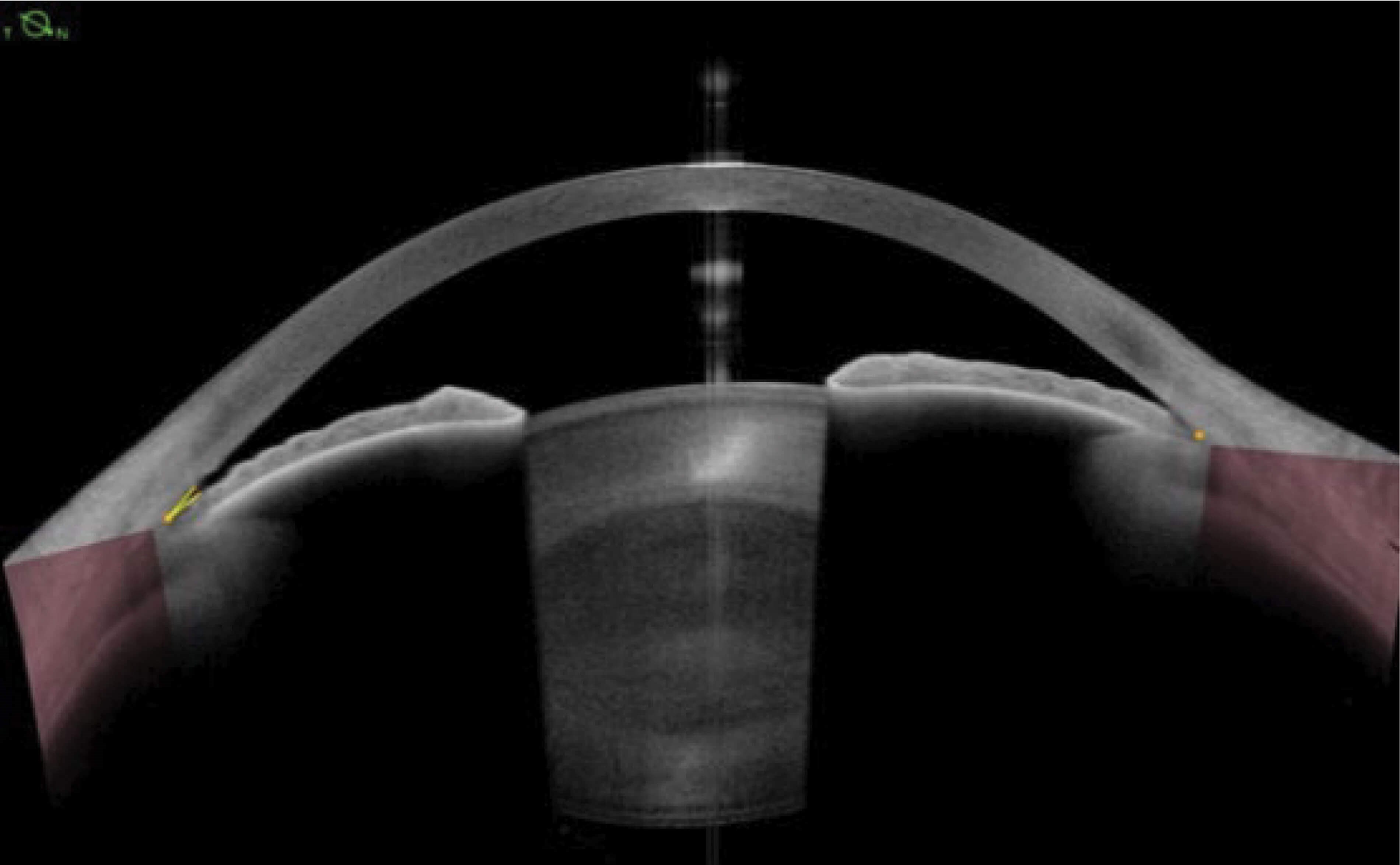
Figure 9c: METRICS OCT of the same patient at the same angle.
Whilst the angle is very narrow on both IMAGING and METRICS in this example, the non-refraction corrected distortion of the iris thickness on the IMAGING OCT falsely gives the interpretation of iridocorneal touch, whereas METRICS OCT analysis gives a scleral spur angle of 11 degrees and an angle opening distance at 500µm from the scleral spur of 0.10mm.
Example 3
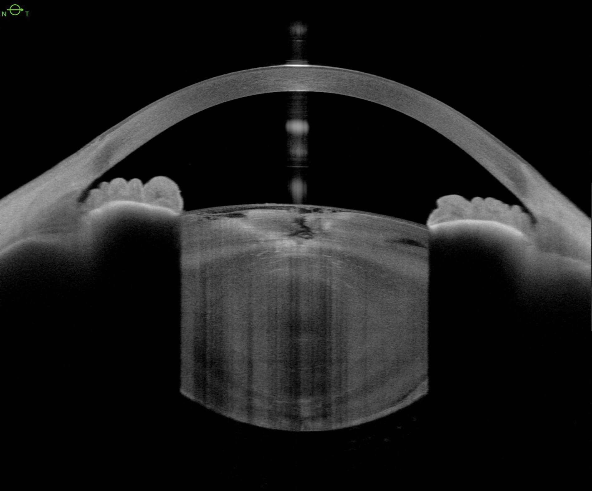
Figure 10a: Horizontal IMAGING OCT.
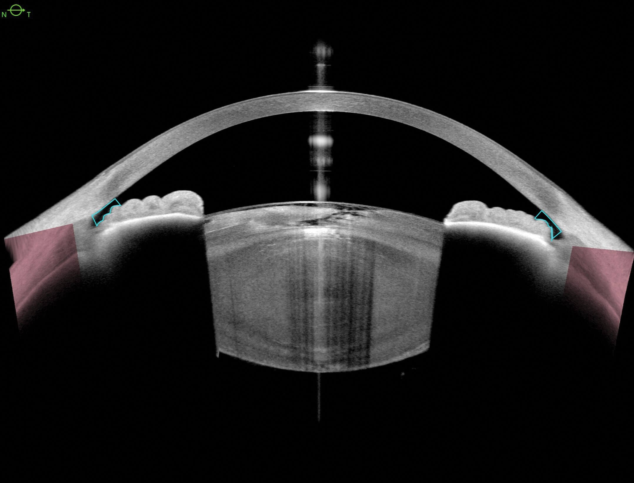
Figure 10b: Horizontal METRICS OCT of the same patient. Note the thicker iris appearance in IMAGING gives the impression of a narrower trabecular iris space (TISA). The blue lines are the TISA 500µm parameters.
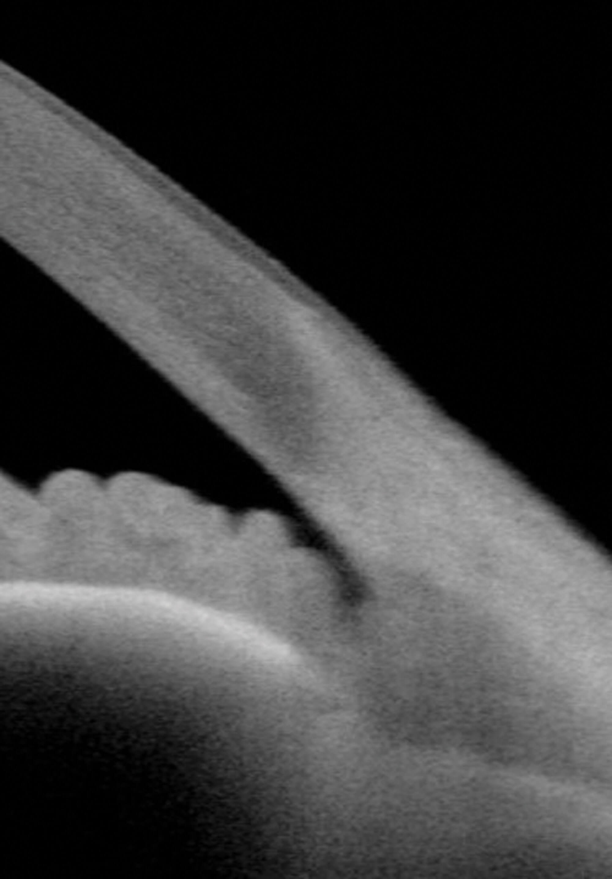
Figure 10c: Magnified view of the temporal TISA in IMAGING.
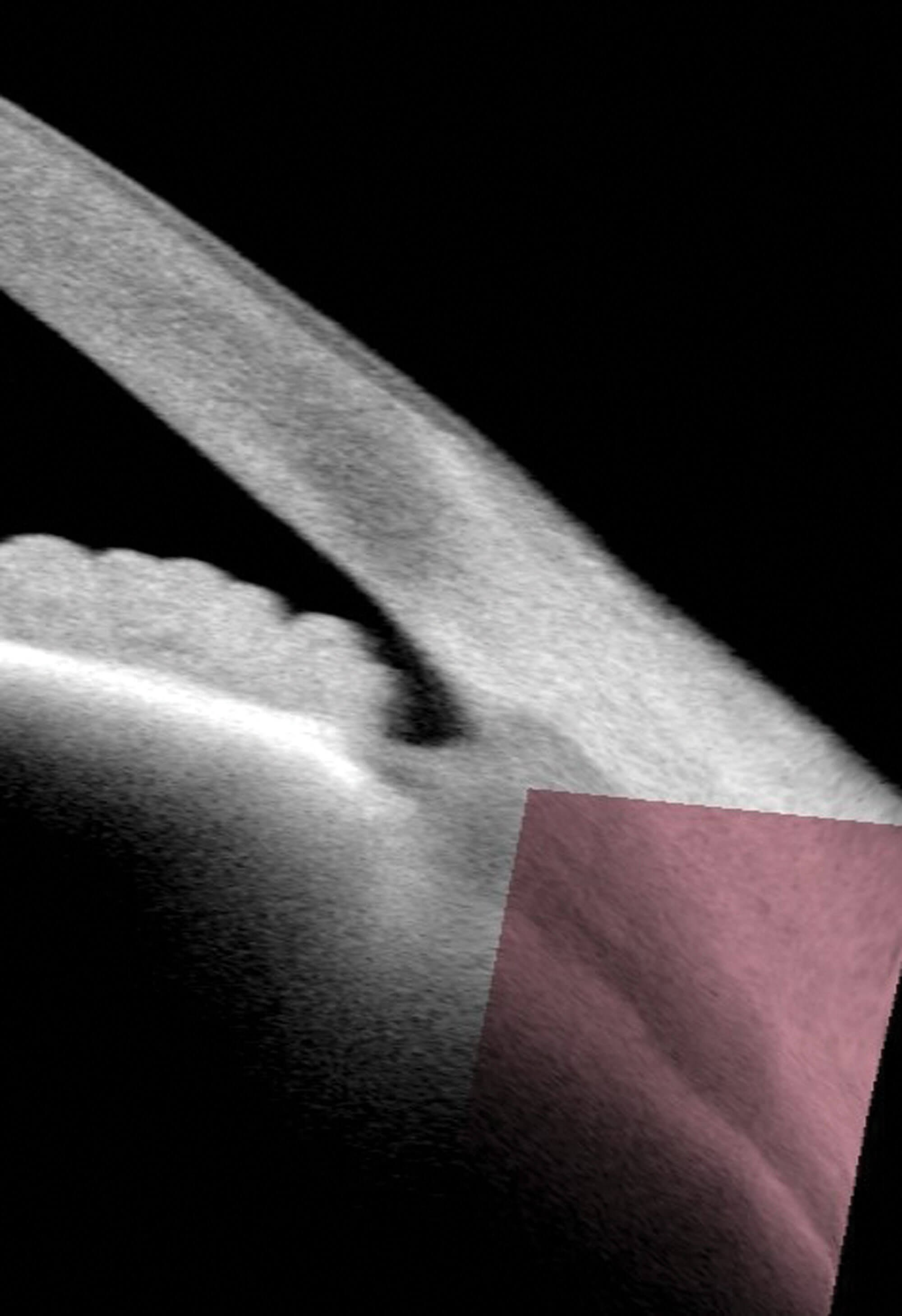
Figure 10d: Magnified view of the temporal TISA in METRICS.
Summary
Swept source AS-OCT is an essential tool for many AS conditions, and standard SS OCT imaging offer excellent visualisation of pathology that occurs in the anterior structures that also offers opportunity for teaching purposes as well as patient education. It is also possible to fine tune and create custom scan patterns to focus on a particular area of interest. However, we can observe in these cases the effect the cornea has on imaging and for clinical monitoring and diagnosis, we should not rely on the imaging alone, and that for clinical confidence in monitoring conditions, accurate, repeatable measurement parameters should be considered as well.
References
1. Mirzayev I, Gündüz AK, Ellialtıoğlu PA, Gündüz ÖÖ. Clinical applications of anterior segment swept-source optical coherence tomography: A systematic review. Photodiagnosis Photodyn Ther 2023;42:103334.
2. Huang D, Swanson EA, Lin CP, et al. Optical coherence tomography. Science 1991;254(5035):1178–81.
3. www.heidelbergengineering.com/en
4. Tian Y, Draelos M, McNabb RP, et al. Optical coherence tomography refraction and optical path length correction for image-guided corneal surgery. Biomed Opt Express 2022;13(9):5035–49.
5. www.menicon.co.uk
6. Woo SL. A coherent strategy for fitting scleral lenses. RCCL 2015;May:30–1.
[All links last accessed April 2026]
Declaration of competing interests: None declared.